Shop Drawings: Essential for Bridge Construction
Shop drawings, also known as fabrication drawings, are detailed plans that translate design intent into instructions that can be used to fabricate and assemble the components of a bridge. They are typically prepared by the bridge contractor or a specialised subcontractor, and must be approved by the engineer of record before fabrication can begin.
Shop drawings are used for a variety of purposes in bridge construction, including:
- To ensure that the fabricated components meet the design requirements. Shop drawings include detailed information on the dimensions, materials, and fabrication methods for each component. This information is used to ensure that the components are fabricated to the correct specifications and will be able to withstand the loads they are designed to carry.
- To coordinate the fabrication of different components. Shop drawings must show how different components will fit together and be connected. This is especially important for complex bridges with many different components.
- To provide guidance to the fabricator. Shop drawings should include all of the information necessary for the fabricator to produce the components accurately and efficiently. This includes information on the types of materials to use, the cutting and welding procedures to follow, and the quality control measures to be implemented.
- To provide a reference for field construction. Shop drawings can be used by the contractor and the engineer to reference the dimensions and locations of components during field construction. This helps to ensure that the bridge is assembled correctly and meets the design requirements.
Shop drawings are an important component of the construction process for various structures, including bridges. In bridge construction, shop drawings play a critical role in ensuring that the design and engineering specifications are accurately translated into the actual construction of the bridge.
Here are some specific examples of how shop drawings are used in bridge construction:
- To fabricate steel bridge girders. Shop drawings for steel bridge girders typically include information on the following:
- The dimensions of the girder, including its length, depth, and flange widths
- The type of steel to be used
- The location of all welds, bolts, and other connections
- The fabrication procedures to be followed, such as the type of welding electrodes to use and the heat treatment requirements
- To fabricate precast concrete bridge deck panels. Shop drawings for precast concrete bridge deck panels typically include information on the following:
- The dimensions of the panel, including its length, width, and thickness
- The type of concrete to be used
- The location of all reinforcing steel
- The fabrication procedures to be followed, such as the curing process and the quality control measures to be implemented
- To fabricate bridge bearings. Shop drawings for bridge bearings typically include information on the following:
- The type of bearing to be used
- The dimensions of the bearing, including its load capacity
- The materials to be used for the bearing components
- The fabrication procedures to be followed, such as the machining tolerances and the quality control measures to be implemented
Here's how shop drawings are used in bridge construction:
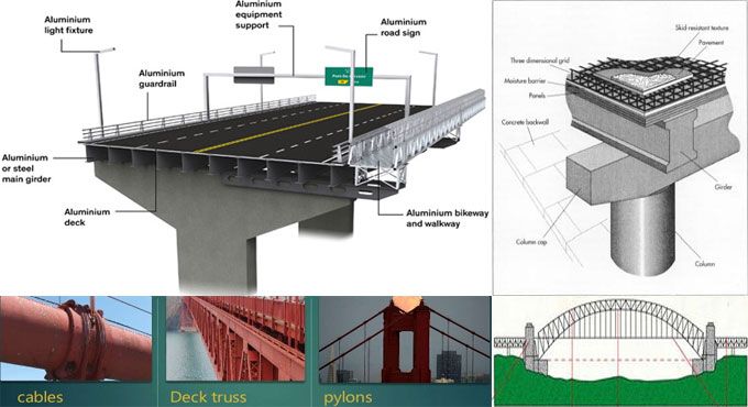
- Detailed Plans and Specifications: Shop drawings provide detailed plans, specifications, and fabrication instructions for various components of the bridge. These components can include girders, piers, abutments, reinforcing steel, bearings, and other structural elements.
- Customisation: Bridge construction often involves the fabrication of custom-made components to meet the specific requirements of the project. Shop drawings allow for customisation and ensure that the fabricated parts are precisely tailored to fit the design and engineering specifications.
- Quality Control: Shop drawings are essential for quality control. They help bridge construction teams ensure that the materials and components used in the project meet the required standards and specifications. This includes verifying the dimensions, materials, and tolerances of various parts.
- Coordination: Shop drawings help in coordinating the work of various trades and subcontractors involved in the bridge construction project. They provide a reference point for different teams, ensuring that they are on the same page in terms of how the bridge components are fabricated and assembled.
- Compliance: Shop drawings serve as a means to demonstrate compliance with the approved design and engineering plans. They are often reviewed and approved by engineers, architects, and other relevant authorities to confirm that the construction process aligns with the initial design.
- Fabrication and Assembly Guidance: Shop drawings include detailed instructions on how to fabricate and assemble the various bridge components. They provide information on welding, bolting, and other joining methods, as well as guidelines for positioning and securing the parts.
- Record Keeping: Shop drawings also serve as a record of the construction process, allowing project stakeholders to track progress, make revisions if necessary, and resolve any discrepancies or issues that may arise during construction.
- Communication: Shop drawings are a critical communication tool between the design team, construction team, and various subcontractors and suppliers. They help ensure that everyone involved in the project is working with a clear understanding of the construction requirements.
- Revision and Updates: As the project progresses, there may be a need to make revisions or updates to the original design and plans. Shop drawings can be revised to reflect any changes or modifications, helping to maintain the accuracy and integrity of the project.
In summary, shop drawings are a vital component of bridge construction, ensuring that the design and engineering specifications are accurately translated into the physical structure. They facilitate coordination, quality control, compliance, and effective communication amongst all parties involved in the construction process.
[edit] Related articles on Designing Buildings
- As-built drawings and record drawings.
- Assembly drawing.
- Bridge.
- Detail drawing.
- Component drawing.
- Concept drawing.
- Design drawings.
- Drawings.
- General arrangement drawing.
- Installation drawings.
- Notation and units on drawings and documents..
- Production drawing.
- Production information.
- Shop drawings.
- Working drawings.
Featured articles and news
Guidance notes to prepare for April ERA changes
From the Electrical Contractors' Association Employee Relations team.
Significant changes to be seen from the new ERA in 2026 and 2027, starting on 6 April 2026.
First aid in the modern workplace with St John Ambulance.
Ireland's National Residential Retrofit Plan
Staged initiatives introduced step by step.
Solar panels, pitched roofs and risk of fire spread
60% increase in solar panel fires prompts tests and installation warnings.
Modernising heat networks with Heat interface unit
Why HIUs hold the key to efficiency upgrades.
Reflecting on the work of the CIOB Academy
Looking back on 2025 and where it's going next.
Procurement in construction: Knowledge hub
Brief, overview, key articles and over 1000 more covering procurement.
Sir John Betjeman’s love of Victorian church architecture.
Exchange for Change for UK deposit return scheme
The UK Deposit Management Organisation established to deliver Deposit Return Scheme unveils trading name.
A guide to integrating heat pumps
As the Future Homes Standard approaches Future Homes Hub publishes hints and tips for Architects and Architectural Technologists.
BSR as a standalone body; statements, key roles, context
Statements from key figures in key and changing roles.
ECA launches Welsh Election Manifesto
ECA calls on political parties at 100 day milestone to the Senedd elections.
Resident engagement as the key to successful retrofits
Retrofit is about people, not just buildings, from early starts to beyond handover.
Plastic, recycling and its symbol
Student competition winning, M.C.Esher inspired Möbius strip design symbolising continuity within a finite entity.
Do you take the lead in a circular construction economy?
Help us develop and expand this wiki as a resource for academia and industry alike.
Warm Homes Plan Workforce Taskforce
Risks of undermining UK’s energy transition due to lack of electrotechnical industry representation, says ECA.
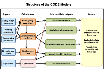
Cost Optimal Domestic Electrification CODE
Modelling retrofits only on costs that directly impact the consumer: upfront cost of equipment, energy costs and maintenance costs.


